Circuits

Level 1

What is electricity?

An electrical circuit is a bit like a road that electric current follows to make devices work. The current must leave an energy source, go through wires and components, then return to its starting point.

In our daily lives, we are surrounded by electrical circuits: the lights in your house, your mobile phone, the television, the refrigerator... All these devices work thanks to circuits that allow current to flow.

The 2 rules for how an electrical circuit works

For current to be able to flow in a circuit, two essential conditions must be met:

Rule No. 1: an energy source, such as a battery or a generator. It is what supplies the current.

Rule No. 2: a closed and continuous path, which allows current to leave the + terminal and return to the – terminal. If there is a break (disconnected wires, open switch), current no longer flows.

Experiment with the circuit!

Electric current leaves the + terminal of the battery, passes through the closed switch, goes through the lamp (which lights up), and returns to the - terminal of the battery. The path is complete, the devices work!
Vectored_Illus
+ -
✅ Closed circuit - Current is flowing! The lamp lights up 💡

Components: circuit components

All electrical devices have two terminals: they are components. There are two main families:

Generators: they produce electricity.

  • Laboratory generator
  • Battery 

Receivers: they use the current's energy.

  • Lamp
  • Motor
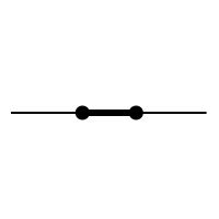
  • Switch
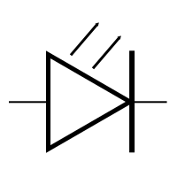
  • LED
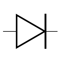
  • Diode
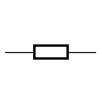
  • Resistor (or ohmic conductor)
Click on a device on the left
Generator
Device name


Short circuits and safety

A short circuit occurs when the current finds a shorter path that bypasses the receiver (for example, a wire directly connecting the two terminals of the battery without going through the lamp).

  The current then becomes very high: the wires get very hot, the battery drains very quickly, and there is a risk of burns or fire.

A few electrical safety rules:

  • Never directly connect the two terminals of a battery with a simple wire.
  • Never touch an electrical device with wet hands.
  • In class, we use batteries (low voltage), never mains sockets (230 V), which are dangerous, or even fatal.


Why use symbols?

So that everyone speaks the same language, scientists created standardized symbols. This allows an electrician, regardless of their country, to understand the same diagram.

Symbols to know

Here are the main symbols used in an electric circuit:

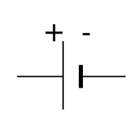
The Battery
Vectored_Illus
Circuit-SymbolePile
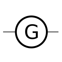
The generator
Vectored_Illus
Circuit-SymboleGénérateur
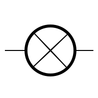
The lamp
Vectored_Illus
Circuit-SymboleLampe
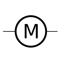
The motor
Vectored_Illus
Circuit-SymboleMoteur
The open switch
Vectored_Illus
Circuit-SymboleInterrupteurFermé
The closed switch
Vectored_Illus
Circuit-SymboleInterrupteurFermé
The diode
Vectored_Illus
Circuit-SymboleDiode
The LED
Vectored_Illus
Circuit-SymboleDel
The resistor
Vectored_Illus
Circuit-SymboleResistor

How to draw a diagram?

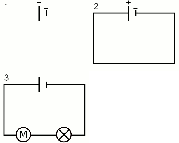
To draw a circuit diagram, always follow these 3 steps:

  1. Draw the generator (usually on the left).
  2. Draw the wires: they form a loop using straight lines (usually a rectangle).
  3. Add the components on the segments, never in the corners.
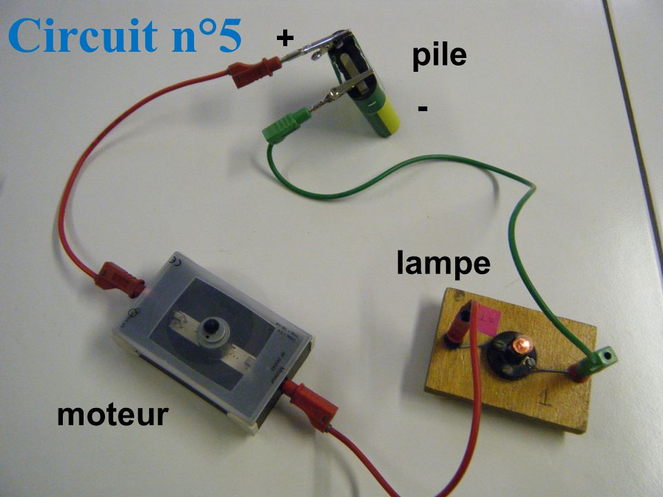
Image
Circuit-Circuit Réel
Image
Circuit-SchNormalisé-GIF

Sensors and energy converters

Some circuits are used to react to their environment. To do this, a sensor is added: a component whose behaviour changes depending on an external quantity.

  • A temperature sensor (thermistor) reacts to heat.
  • A light sensor (photoresistor, or LDR) reacts to light.
  • A motion sensor detects movement.

  Example: a street light equipped with a light sensor turns on by itself when night falls.


Energy converters

A receiver component is an energy converter: it receives energy and converts it into another form of energy. We speak of input energy and output energy.

  • Motor: electrical energy   motion
  • Lamp / LED: electrical energy   light (and a little heat)
  • Photovoltaic cell: light   electrical energy

  The photovoltaic cell works "in reverse" to a lamp: it receives light and produces electricity.


Current loops

A loop is a path from the + terminal to the - terminal that the electric current could follow. It is therefore the path taken by the current, assuming the circuit is closed (even if it is open), to move from the generator, through the wires and components, until it returns to the generator.

If the circuit contains several loops, this means that there are several paths, the current can take several different paths at the same time.

Visualisation of current loops:
Vectored_Illus

Series or parallel connection?

In Series

In a series connection, all components are placed one after the other, on a single loop. The current flows through each component in turn. If a component is removed or blows, the entire loop turns off.

  Example : Old Christmas lights 
  If one bulb blows, everything goes out.

Click on a component to simulate a fault

Vectored_Illus
M

In Parallel

In a parallel connection, several independent paths exist. Each component can be on a different loop. If a component stops working, the others keep working.


  Example : House lighting 
 If the living room bulb blows, those in the other rooms still work.


Click on a component to simulate a fault

Vectored_Illus
M


Nodes and branches

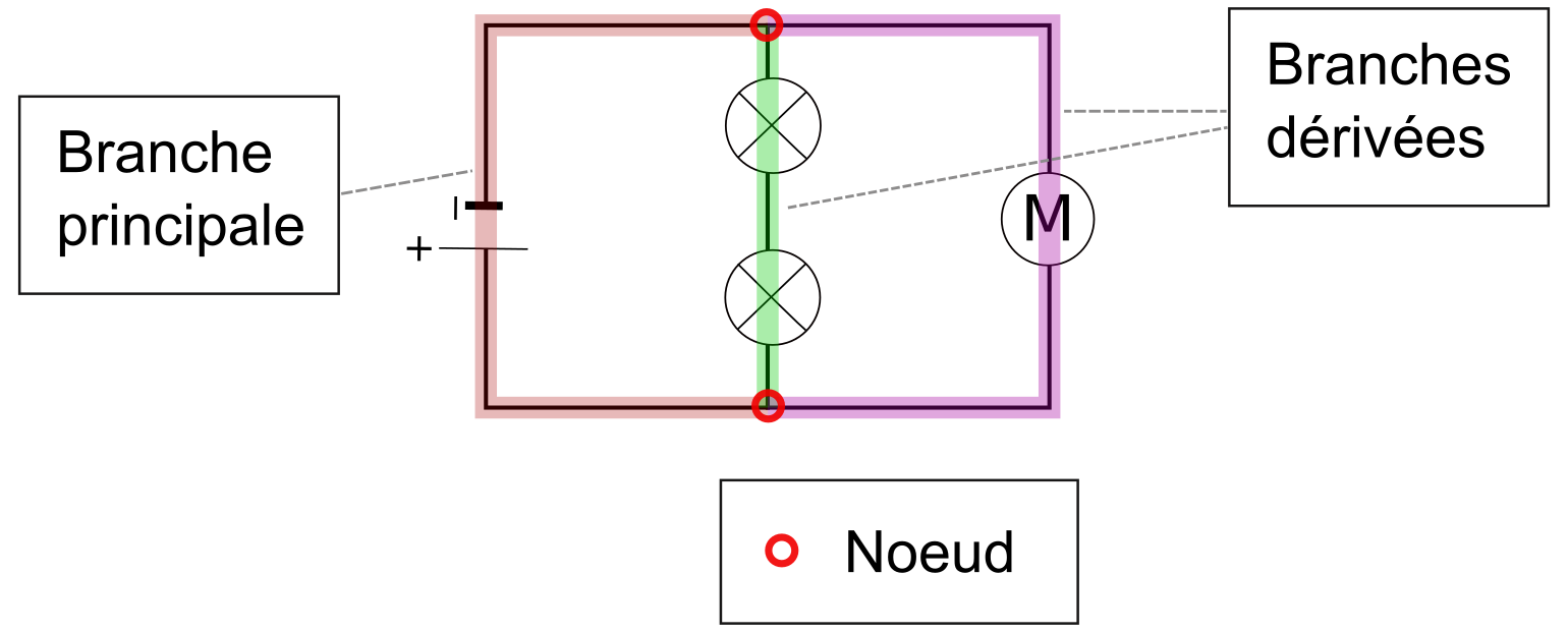
In a circuit, a node is a point where three or more wires meet. It is like a junction: the current can split or come together there.

Image
Circuit-Description

A branch is a portion of a circuit between two nodes, containing at least one component.

We distinguish:

  • The main branch: the one that contains the generator. It belongs to all the loops in the circuit.
  • The parallel branches: all the others.