Electricity

Level 1

What is a conductive material?

Electricity does not flow everywhere: it needs a path made of materials that let it pass through.

We then speak of electrical conductivity.

  Definitions:

  • A conductor is a material that allows electric current to flow.
  • An insulator is a material that prevents electric current from flowing.

  Examples:

Metal is a conductor: a stainless steel spoon, a copper wire…

METAL
(Conductor)

Plastic is an insulator: it surrounds cables to prevent shocks.

PLASTIC
(Insulator)

Analogy (imperfect but helpful!): 
Electricity can be seen as cars on a road: the road (conductor) allows cars to pass, a wall (insulator) blocks them.

What is an electrical quantity?

Certain effects of electricity in a circuit can be measured using quantities: it is like taking the "vital signs" of the current.

Electric current

Current measures the amount of electricity flowing through a circuit at any given moment. Its symbol is I.


It is measured in Amperes, abbreviated A, with a device called an ammeter (whose symbol is shown on the diagram).
The ammeter must always be connected in series with the component in order to measure the current passing through this same component.

Simulator: Electric current

Vectored_Illus
A

Current: 0 A
Status: Normal

Voltage

Voltage represents the difference in electrical charges between two terminals. It is what allows the current to set itself in motion. Its symbol is U.

The higher the voltage, the more "push" the current has to flow.

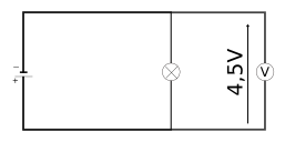
It is measured in Volts, abbreviated V, with a device called a voltmeter.

The voltmeter must always be connected in parallel with the component in order to measure the voltage across the terminals of this same component

Vectored_Illus
Electricite-TensionVoltmètre


Analogy (imperfect but clear!): 
Current is the number of cars driving on the road; 
Voltage is, for example, the difference in location of the cars during the summer holidays. The cars residing in the center of the country move towards the coasts because there is the sea!

The junction rule

A junction is therefore a point in the circuit where at least 3 wires meet. Electric current is never lost and never builds up: all the current entering a junction leaves it. This is the junction rule. Let's see what it gives in both types of circuits.

The junction rule in a series circuit

In a series circuit, there is no junction: the current has only one possible path. When measuring the current, we therefore notice that it remains identical at every point in the circuit.

  Example: in a circuit with a battery, two lamps and a motor in series:

  • At the battery output, the current is IP
  • After lamp 1, the current is I1
  • After lamp 2, the current is I2
  • After the motor, the current is IM

We observe that: $I_P = I_1 = I_2 = I_M$

➡ Without a junction, only one path, only one current: this is the junction rule in a series circuit. It is also called the law of uniqueness of current.

Series circuit - Current visualization

Vectored_Illus
M
Imotor = 0.3A
IL1 = 0.3A
IL2 = 0.3A

The junction rule in a parallel circuit

In a parallel circuit, the current splits at each junction between the branches. Since everything entering the junction leaves it, the current in the main branch is equal to the sum of the currents in the parallel branches.

  Example: circuit with a battery and two lamps in parallel:

  • In the main branch (with the battery), the current is IP
  • In branch 1: I1, in branch 2: I2

We observe that: $I_P = I_1 + I_2$

➡ This is the junction rule in a parallel circuit. It is also called the law of additivity of current.

Parallel circuit - Current visualization

Vectored_Illus
M
Imain = 0.9A
Ibranch1 = 0.5A
Ibranch2 = 0.4A

Kirchhoff's Voltage Law (KVL)

Loops are sometimes also called meshes. In each loop, the battery voltage is distributed among the loop's components:

Ubattery = sum of voltages across the loop's components
This is Kirchhoff's Voltage Law. Let's see how it applies to both types of circuits.

Kirchhoff's Voltage Law in a series circuit

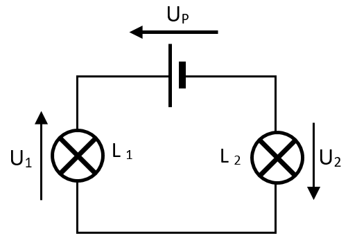
A series circuit contains only a single loop: the battery voltage is shared across all components.

  Example: battery and two lamps in series:

  • Voltage across the battery terminals: UP
  • Lamp 1 voltage: U1, lamp 2: U2

We observe that: $U_P = U_1 + U_2$

➡ This is Kirchhoff's Voltage Law in a series circuit. It is also called the voltage additivity rule.

Image
Loi des Tension - Série

Kirchhoff's Voltage Law in a parallel circuit

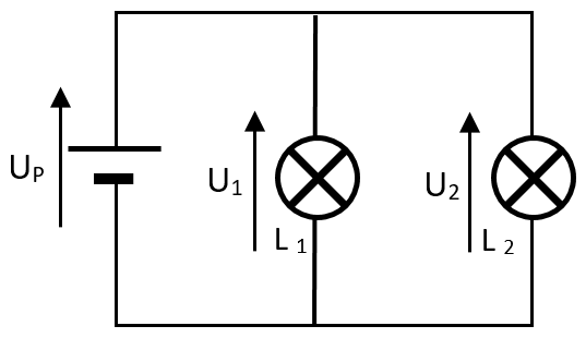
In a parallel circuit, each loop contains the battery and a single component. Kirchhoff's Voltage Law then states: the voltage across the battery is the same in each branch.

  • We observe that: $U_p = U_1 = U_2$

➡ This is Kirchhoff's Voltage Law in parallel. It is also called the voltage equality rule.

Image
Loi des tensions - Dérivation

Electrical Resistance

Resistance is the ability of a two-terminal component or material to oppose the flow of electric current. It is denoted by R.

The more resistive an object is, the less current flows. Conversely, if it has low resistance, it allows current to flow easily.

Resistance is measured in Ohms (Ω).

Measuring Resistance

An ohmmeter is used. This device must be used disconnected from the circuit—without any current source! Its electrical symbol is shown opposite.

Ohm's Law

There is a mathematical relationship linking voltage (U), current (I), and resistance (R).

Plotting voltage as a function of current for a resistor yields a straight line passing through the origin, indicating a proportional relationship:

$$U = R \times I$$

This can also be written as:

  • $ R = \frac{U}{I} $
  • $ I = \frac{U}{R} $

Power: energy per unit time

Power represents the amount of energy consumed (or supplied) per second.

It is denoted by P and is expressed in watts (W).

Example: a 100 W lamp consumes more energy than a 40 W lamp for the same time taken.

Power and energy

Power can be related to energy and time using the formula:

$$P = \frac{E}{t}$$

  • P: power in watts
  • E: energy in joules
  • t: time in seconds

Electrical power in a circuit

In an electrical circuit, power can be calculated using voltage (U) and current (I):

$$P = U \times I$$

  • U: voltage in volts
  • I: current in amperes

Power and Energy

💡 40W Bulb
P = U × I
P = 20V × 2A = 40W
Voltage: 20V
Current: 2A
💡 100W Bulb
P = U × I
P = 20V × 5A = 100W
Voltage: 20V
Current: 5A
⏱️ Time elapsed: 0 seconds
⚡ Real-time energy consumption
40W Bulb
 
0 J
100W Bulb
 
0 J

  A useful... or dangerous effect
- Desired in heating appliances: electric heater, toaster, kettle, iron, hair dryer, filament bulb.
- Feared in wires and power strips: too high a current causes them to heat up, the plastic sheath can melt or burn. This is why overloading a power strip must be avoided (fire hazard).